About Dieter Munkes

This author has not yet filled in any details.
So far Dieter Munkes has created 23 blog entries.

Prototyping

By |2019-09-08T19:18:29+01:00September 8th, 2019|Uncategorized|

just testing….

Ing. Buero Dieter Munkes News   •   June 2, 2016

Neue Ansätze ausprobieren erfordert das man mal schnell etwas aufbaut.

Die ganze Story.

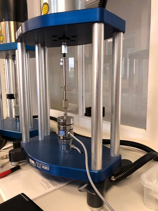
In 2010 wurde eine Prüfmaschine für eine EN14801 (Lebendauer Zahnimplantate ) entwickelt.

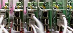
Damals mit automatisierungs Komponenten von Beckhoff, eigenem Leistungsteil und Vorverstärkern.

Im Verbund mit 8 Prüfstationen kann eine SPS das leicht handhaben. Mit weniger Stationen wird der Kostenanteil der Steuerung überproportional groß.

Die Lösung bestand aus Beckhoff IO, SPS , einem PC Win7 sowie einer Betriebsoftware geschrieben unter Delphi.

Folgende Nachteile: Einen PC mit allem Security updates.. die Enduser installieren zusätzliches, binden diesen ins Unternehmesnetzwerk ein.

Dies mag bequem sein, wird aber gerne zum Pflegefall.

Ziel 1-2 Stationen?

SPS -> zu teuer für Serie.

PC -> zu teuer bez. Wartung und pflege.

Messtechnik könnte Rauschärmer sein->Neubau

Da wäre als neuer Ansatz die SPS auf einen Microcontroller zu verlagern. Den PC gegen einen Raspberry zu tauschen. Die Benutzeroberfäche mit allen Grafiken in HTML5.

Fazit-> Wirklich alles neu machen.

Zur Abschätzung der Risiken wurden ohne nenenswerten Hardware Invest einige Tests gemacht:

SPS-Code in 1ms Timerinterrupt verlagern -> geht 20% load

Kommunikation Microcontoller zu PC per USB -> 1,6MByte/s, Bedarf 64KB/s

Einbindung Microcontoller an Raspberry -> geht ohne zusätzliche Treiber

HTML5 Website zur Bedienung-> nach 4 Wochen probieren , geht (Canvas und WebSocket)

Verbindung von Microcontoller , Datenaufbereitung und Verbindung zur Website per Websocket und JSON geschrieben in Python. Geht

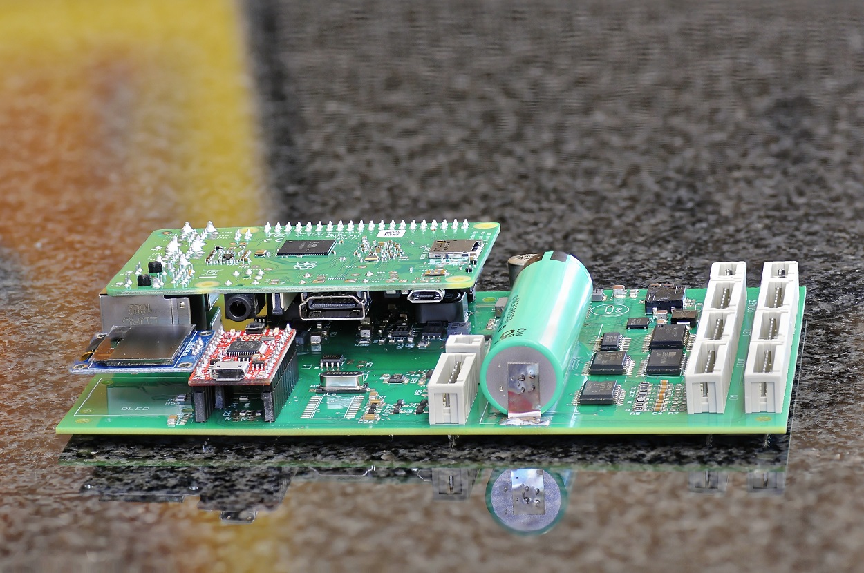
So nun alles auf ein Board und die eigendliche Enwicklung beginnt.

Tools: C auf dem Controller, Python auf dem Pi und HTML5 für die Seite.

Auf dem Board sind Netzteil, USV, OLED, AD7730, DA, Micocontoller, 24V IO, RFID.

Das Board ist auf Anfrage erhältlich.


Calculation of measurement uncertancy

By |2018-05-23T15:36:29+01:00May 23rd, 2018|Uncategorized|

Calculation of measurement uncertancy

Ing. Buero Dieter Munkes News   •   June 2, 2016

During a project to gain accreditation (EN17025) for a laboratory i need to calculate the uncertancy of a measurement system.

I found that there are 2 ways to do it:

A) Get a lot off samples and do some statistics.

B) Get all uncertancy of influencing parameters and calculate a common result.


First create a map of influences. Ishikawa diagram or something like a mindmap.

Set in all parameters inclusive your reference. (Temperature, light, humidity…..)


Goto B)

Now i see that i don´t find exact parameters for the uncertancy parameters. You may assume them. But i don´t like this.

I found that my amplifier has 18ppm/K drift, ok I know the range. But there are drift from DMS, thermovoltages at contacts….

I got crazy with endless unknowns.


The way i found was: Take what you get on B) and do the remaining with A)


I my example it is a machine for testing lifetime of tooth implants. It´s a motor generating force down on an implant.

In series to this is a DMS Force Bridge. For regulation the force. See the first picture.

Now I put additional a reference sensor in series.

The uncertancy and calibration data are known by a Dakks calibration sheet.

I set the system to press with 100N down.

Now i put both sensor data into a histogramm seen on the second picture.

Now i calculate average and standardderivation from my internal sensor.

I calculate average from my reference.

I have the uncertancy from the calibrationsheet of the reference at 100N

So the common uncertancy is =sqrt(  (ref uncertancy)² +(AverageSensor-Averageref)²+(derivation internal sensor)²)

As both are gauss shaped i can expand the range to cover 99% of samples by a factor around 2.7


With this i can say that the system get 99% of samples within +-0,6N at 100N force.

To cover all influences you need to be sure that this influence ocure.

I let the system sample overnight to get a full daily temperature cycle.


Dieter Munkes


Recognizing dental implants in blister

By |2018-04-18T13:33:04+01:00April 17th, 2018|Uncategorized|

Recognize dental implants when they are packed in blister.

Ing. Buero Dieter Munkes News   •   June 2, 2016

One day it happens that one implant was wrong labeled. Ok you would think, “not a problem” . But think about a doctor who find out this after he drilled the hole. As patient you would not be amused.

Due to this risk I got the order to compare implants in glastube and blister against known parameters.

We descided to check length and diameter.

After tests, we saw that you need to change lightning (angle and intensity) for every edge to measure.

With this we build a lightning with contolled 16 LED around the blister.

From top a industrial 5M Pix camera, a Beckhoff industrial PC and some IO to contol the LED.


How does this work ?

We learn at a sample blister the dimensions and the lightning. Its a manual process.

We store this parameter with the given productname.

Now before labeling on a conveyor belt we get the productname from the labeling machine.

Load the parameterset, redo measuring and compare.

Now we give back “good or bad” to kick the blister off the conveyor belt.

Key to this application was the right lightning.


When to use 2D or 3D Data for recognition

By |2018-04-19T22:11:41+01:00April 11th, 2018|Latest Articles|

When to use 2D or 3D Data for recognition

Ing. Buero Dieter Munkes News   •   June 2, 2016

3D scan, laser welding

2 optical technologies are actualy used for inspection or recognition. There is photo camera and the  3D measurement in different ways.

First a few words about photo camera.

Today I use TPC/IP camera for easy connectivity. USB3 would be ok to.On market you get fooded by cheap cameras.

Let´s compare a little.


What are the differences:

The industrial Version have:

  • Bigger lenses = more light , less deeps of focus!
  • Bigger amount of possible lenses
  • Flash trigger output
  • very short exposure times (32usek)
  • Global shutter
  • Monochrome Sensors to avoid Bayer interpolation.

The cheap ones have:

  • very small sensors and lenses = less light but deeps fokus is fine
  • mostly fixed lens
  • no flash
  • rolling shutter and with this unusable on moving objects.
  • normaly color sensor

Extracting the details from the picture you needed for your propose depends on ilumination.

This is the key to success. You can not compensate any wrong lightning by software.

Mostly I need to switch different lights in different positions to get a picture for every parameter i want to extract.

(You use both eyes and/or move your head to do the same)


Let´s go to 3D


I worked with different kind of sensors:

  • Time of flight of a scanned Laser (slow)
  • Time of flight camera like sensor (low resolution)
  • Reflected Laserline under constant angle. (medium fast)
  • projected pattern (never tried this)
  • Dual camera like our eyes (never tried this )

All of this methodes have different ranges and accuacy.

But common is they are all more expensive than an photo camera.

From view of software, in 3D data it is more easy when to find edges , objects.

There is no foreign light no reflections. (Laser systems)

But, no colors, nothing like photo flash.


Now my selection of method.

2D camera

  • low budget
  • low requirement
  • fast
  • recognition not measure


3D sensor

  • control robotics handle 3d results
  • measure deeps or size or distance

You can measure with 2D camera too but mostly need  telecentric components. This easily explode your budget.

Sometimes i need both when it comes to measure and color.


Tiny espresso machine

By |2018-04-21T22:46:21+01:00April 10th, 2018|Uncategorized|

Tiny espresso machine

Ing. Buero Dieter Munkes News   •   April 10, 2018

The lack of a good espresso during my holiday travels brings up the idea to build an own machine.

A fun, non profit project between Christmas and New year.

Requirements are easy for this:

  • Produce espresso
  • Weight almost nothing. Size almost nothing.
  • No open coffee powder handling.


Technical I need:

  • >10Bar
  • >80°C
  • 20-40ml Water.

Solution:

As I go out for diving during my holidays, there is the option to take the middle pressure from my regulator 9.5Bar. Nearly perfect.

Hot water on diveboats is mostly available. For handling coffee i took aluminium capsules.


Sounds easy but i need 2 designs to get it done.

The Solution is 50mm diameter x 65mm tall.

Build out of titanium.

Issues:

  • Main issue is to keep mechanical stength and keep your coffee hot.
  • If i do a classic calculation, i gets over 100kg force on top and bottom. I need to get the tube up to 1.5mm stength….
  • Take Aluminium and you get a coffee only worm, but hot fingers.


Now it works fine.


Lifetime test equipment with BroadR-Reach

By |2018-04-19T22:03:20+01:00December 18th, 2017|Uncategorized|

Testequipment with BroadR-Reach

Ing. Buero Dieter Munkes News   •   Sept 2, 2017

Actual communication in cars changes. We know LIN , CNA over the years, but now we are moving to BroadR-Reach.

Some words about:

  • Developed to cover the last mile in connecting houses.
  • 100Mbit over 2 twisted wires.
  • classic TCP/IP with changed physical layer.
  • Chipset is cheap and avaliable.

Sound fine , but what is the physical parameters for use in a car?

TPC/IP is pear to peer. There is no big switch in the middel of a car.

Every device has to have minimum 2 ports and a kind of switch. (chaining)

With this it can pick the interesting informations out of the stream and route the remaining.


Build test equipment

We got the order to build a tester with 6 simultaus devices running in climate-chamber.

They need to hold in sleep and life state, measure parameters and communicate to get errors and function tests.

BroadR-Reach can be done by media converter.

Fine so far, just one PC, one switch and 6 media converter…. we offered.

During setup we found:

  • All devices have the same fixed IP adress and same MAC-adress.
  • NO router in the world will handle this (or get real expensive)
  • The device sends everthing with TTL=1 -> no one route this
  • It uses for network keep alive multicast and for camera data broadcast.
  • Data content was like CAN over TPC

How we got this done:

We took 12 Raspberry PI on boards with UPS in one row. Add additional NIC to them.

Write some services in python for moving and nating  data between the networks.

With this the PC see everything in a normal network. The PC see every device now in it´s own range.


Finally, everything was fine. But we learned again that automotive may be special.


Designing or testing?

By |2018-04-19T22:03:45+01:00March 10th, 2017|Latest Articles|

Designing or testing?

Ing. Büro Munkes News •   March 10, 2018

S

ometimes i get asked if i can design something and save the costs for testing.

In this article i will write about.

Yes and no should be my answer to this question. I can design and today a can simulate a lot. But, not everything. Very fast, things gets to complex for simulation. Generally simulation supports design to be sure that the design stays in requirements. But at least only testing will prove this and therefore testing is the way to validate design aginst requirements. 

On the other hand, testing soon gets real expensive. Testing should be limited by a solid riskmanagement.

Yes, this sounds crasy but we are talking about spending money to reduce risk of failure.

Let´s look at both extrem ends of this way….

Full risk, no tests, not even when they are mandatory by law. How long will this company exist? You will find such products from off-shore with no company label on it or with fake label. It´s a fire and forget buisnessmodel.

No risk, and you will be never on market in no time and you need gigantic budget.

In the middel of this you find the level of compromice with riskmanagement.

Input will be requirements by law (FCC,CE…..) and product requirements.

For every requirement setup a row in your risksheet.

What could happen, cost of mitigation(test), cost if happend, propability of risk, possible trigger of risk, descission of prevent or absorb risk.

With this you get a clear view of what to test.


Keep It Simple

As projectmanager i can tell you, it´s classic riskmanagement, not more.

And that´s not complicated.

1. Setup risk list

2. Get the costs for Tests and decide about risk/test

3. Set priority accourdingly to the results of your list.

4. Calulate your budget.


Go to Top